The Missing Link: Calibrating a Sparse RGB Rig with OptiTrack
It has been a long time since I last wrote a blog post. Honestly, I almost stopped. In the age of LLMs, writing about technical topics feels pointless. Whatever you want to know, an AI will explain it more clearly and faster than any blog. So why bother?
What changed my mind was running into a problem where AI could tell me the theory perfectly well but couldn’t tell me what actually went wrong when I tried it. That gap only gets filled by doing it: wiring two physical sensor systems together, watching them disagree, and working out why. That kind of experience doesn’t live in training data yet. Physical AI is full of it.
This post is about calibrating a room-scale sparse RGB camera array so that 3D positions tracked by a motion capture system can be projected onto each camera’s image.
Background
The setup uses OptiTrack for 3D motion capture: precise, high-frequency 3D positions of retroreflective markers. The goal is to project those positions onto the image plane of any RGB camera in the room, which means each camera needs to have its pose expressed in the OptiTrack world coordinate system.
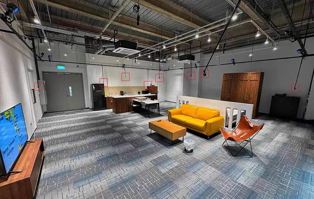
The RGB cameras are eight ZED One units mounted sparsely around a roughly 9 × 9 meter room, on opposite walls, ceiling corners, and so on. Most pairs of cameras have almost no overlapping field of view. Standard multi-camera calibration assumes co-visibility: both cameras observe the same target at the same time, which ties their coordinate frames together. That assumption breaks down completely here.
The OptiTrack system also comes with twelve Prime x22 infrared cameras that are internally calibrated. Using them as an intermediate bridge sounds appealing, and after some false starts it became a key part of the solution. The two catches: the exported calibration stores camera orientations in an OpenGL-style convention that has to be flipped before the extrinsics make sense to OpenCV, and the per-camera calibration carries enough cross-camera inconsistency that it can only be trusted in aggregate, not frame by frame. More on both below.
Hardware and Calibration Target
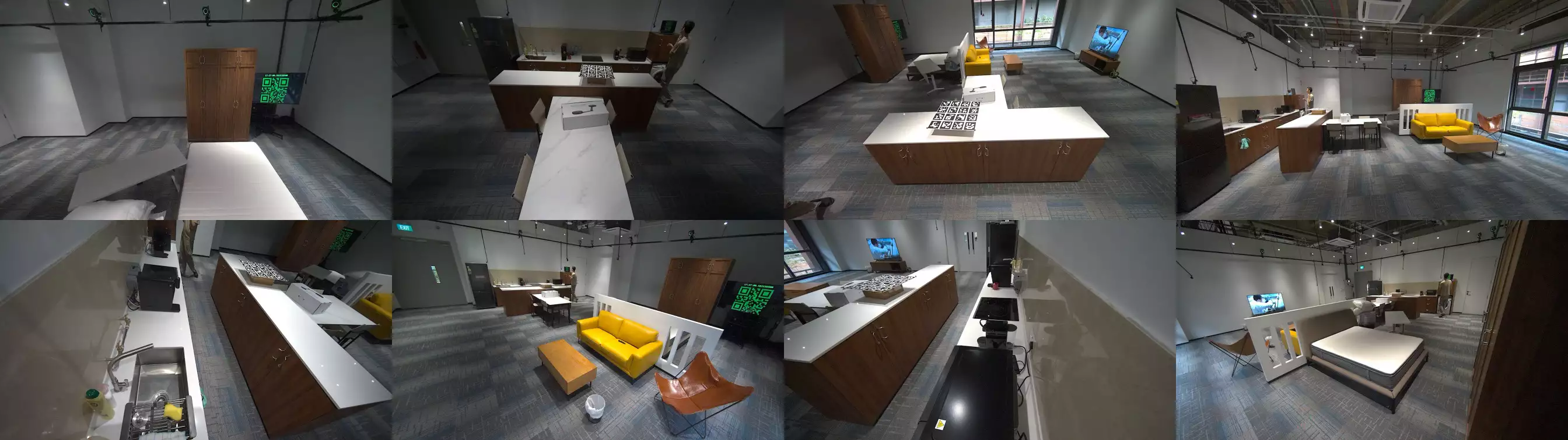
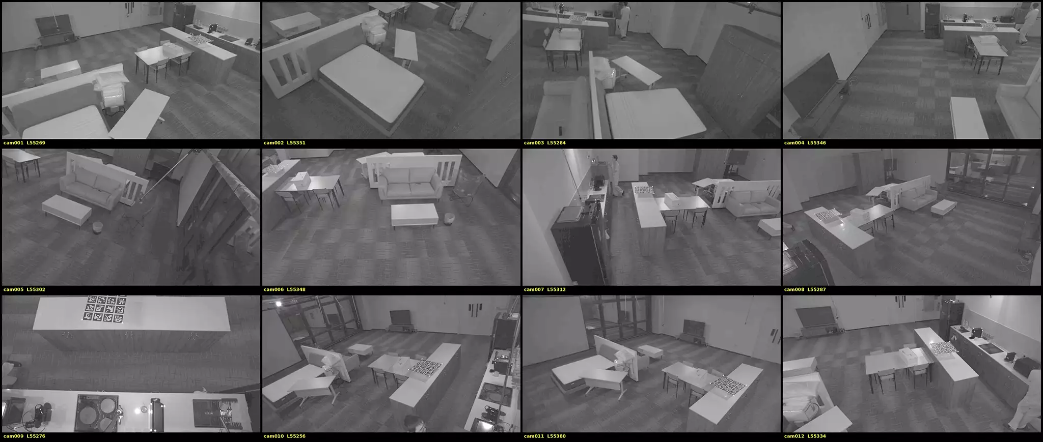
Cameras. The RGB side is eight ZED One cameras (1920 × 1080, color). The motion capture side is twelve OptiTrack Prime x22 infrared cameras (2048 × 1088, monochrome). The two systems record on different machines with different clocks. How their frames get matched up is covered in the next section.
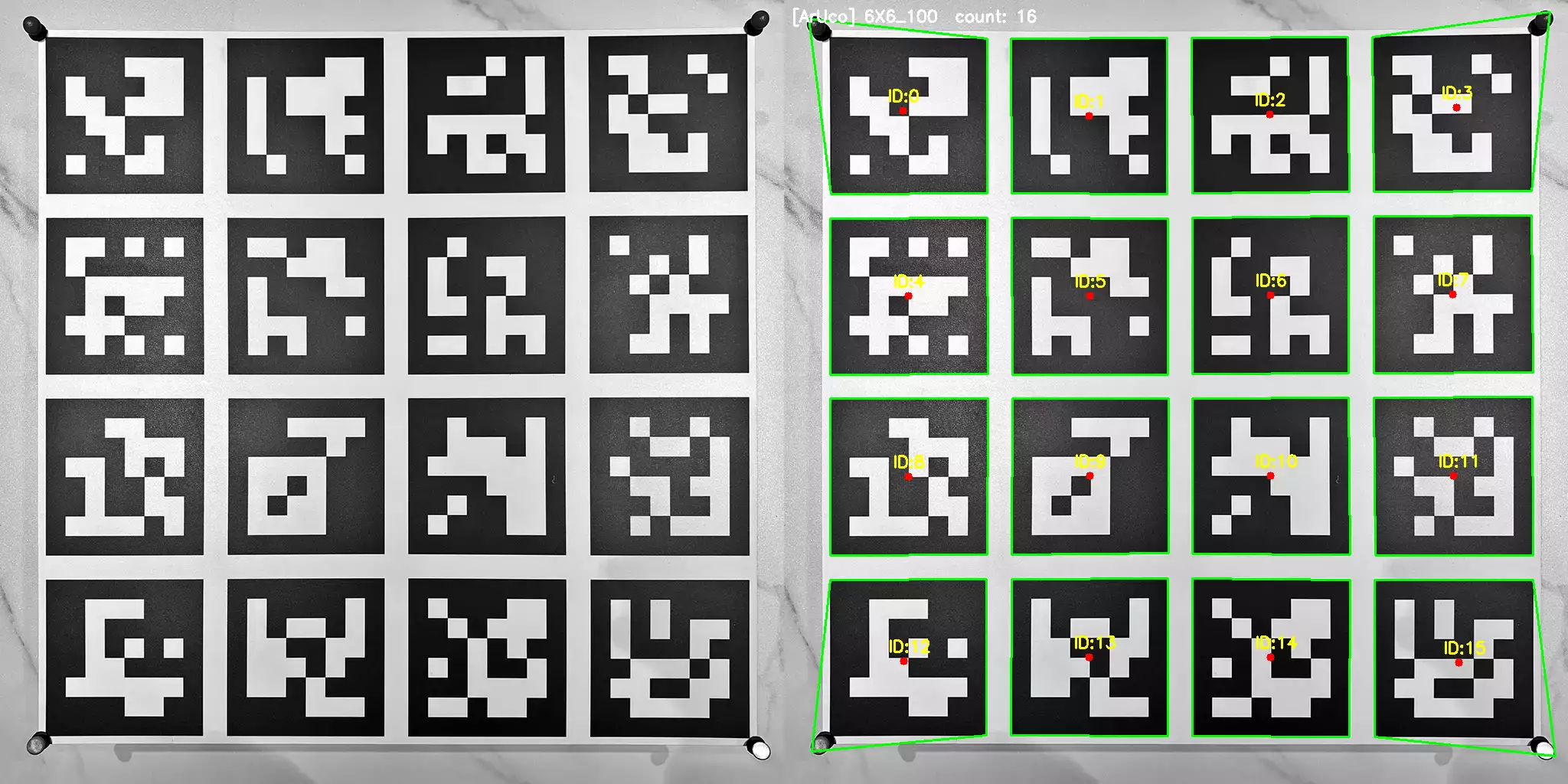
Calibration board. The calibration target is a 4 × 4 grid of ArUco markers 1 (DICT_6X6_100, IDs 0–15), each 125 mm with 25 mm gaps between them, printed on a forex board (rigid PVC foam, matte white surface). Forex is important here: unlike paper, it reflects infrared light well enough that the board stays clearly visible to OptiTrack cameras without needing extra treatment.
At each corner of the board, a retroreflective OptiTrack marker is attached. This makes the board visible to both systems at once: ArUco for the RGB cameras, and the four corner markers forming a rigid body for OptiTrack. One physical object, two independent observations. That’s the core of the whole approach.
Synchronized Capture
Before any calibration can happen, both systems have to record the same moments, and we have to know exactly which frame corresponds to which. The board moves at a few hundred mm/s while being carried, so a single OptiTrack frame (16.7 ms) of misalignment already shifts it by several millimeters. A mismatch of a dozen frames would produce errors larger than everything else in this post combined.
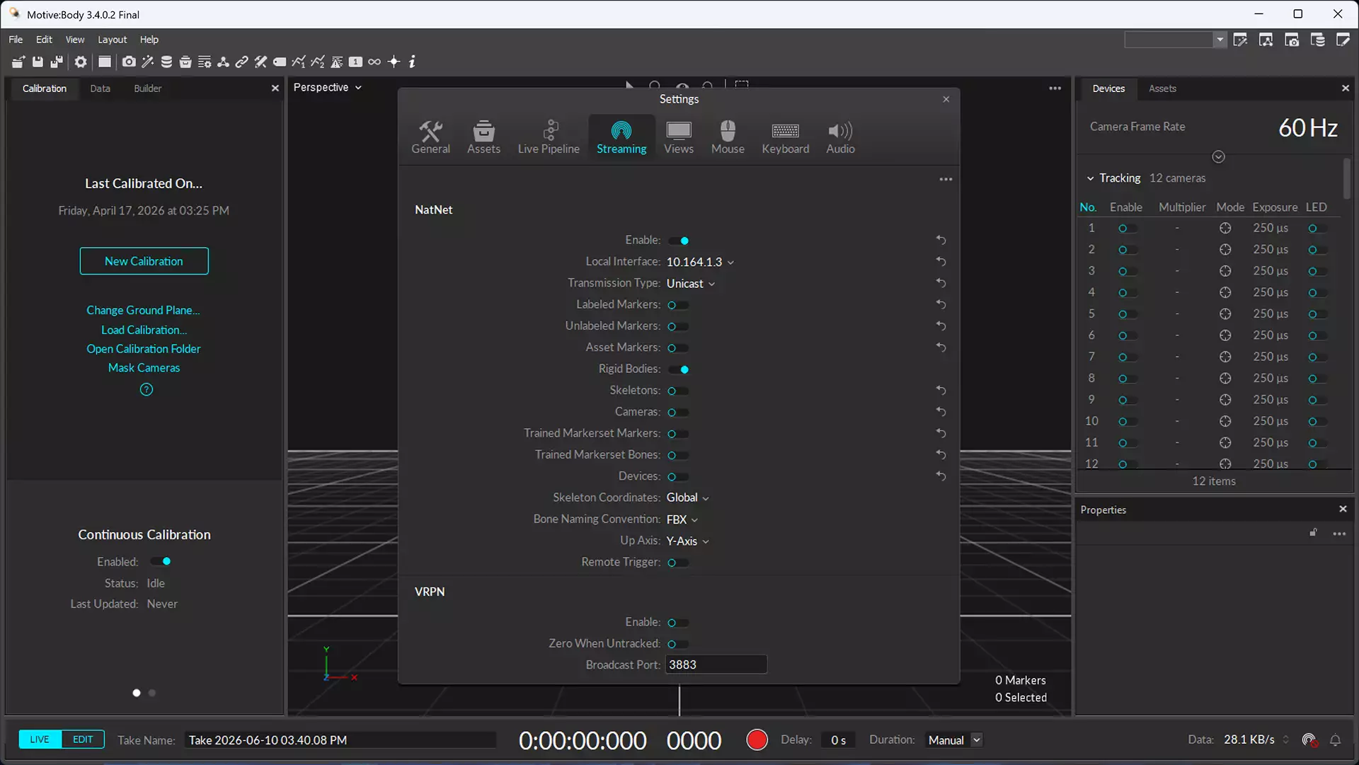
Starting both recordings together. The ZED side records on a Jetson Orin; the OptiTrack side records in Motive on its own PC. The two are coordinated over the network via the NatNet SDK: the Orin subscribes to Motive’s data stream, detects the instant the operator presses Record in Motive, and only then starts grabbing ZED frames. When Motive stops recording, the ZED recorder notices and stops itself. For this to work, the NatNet broadcast must be enabled in Motive first: open Edit → Settings → Data Streaming, enable Broadcast Frame Data, and set the Local Interface to the IP reachable by the Orin (see screenshot below).
The trick for detecting Record without any extra protocol is that Motive’s frame counter resets when recording starts and jumps forward when it ends:
class MotiveSync:
    """Subscribes to Motive's NatNet stream; detects recording start/stop."""

    def __init__(self, server_ip, client_ip):
        self._client = NatNetClient()
        self._client.set_server_address(server_ip)
        self._client.set_client_address(client_ip)
        self._client.new_frame_with_data_listener = self._on_frame
        self._had_recording = self._recording_stopped = False
        self._last_frame_number = None

    def _on_frame(self, frame_data):
        t_arrival_ns = time.clock_gettime_ns(time.CLOCK_MONOTONIC)
        frame_number = frame_data["frame_number"]

        # Motive's frame counter resets when "Record" is pressed and jumps
        # forward again when recording stops. That's the start/stop signal.
        if self._last_frame_number is not None:
            delta = frame_number - self._last_frame_number
            if delta < -100:
                self._had_recording = True            # recording started
            elif self._had_recording and delta > 100:
                self._recording_stopped = True        # recording ended
        self._last_frame_number = frame_number

        if self._had_recording:
            # Log arrival time + Motive timestamp + mid-exposure ticks
            # for the post-hoc clock offset / drift analysis.
            self._log(t_arrival_ns, frame_number, frame_data["timestamp"])


for zed in zeds:                       # open all cameras first (slow),
    open_camera(zed, fps=30)           # so the wait below overlaps it

motive = MotiveSync(motive_server_ip, orin_ip)
motive.start()
motive.wait_for_first_frame()          # blocks until Record is pressed

for zed in zeds:                       # grab threads start only now, so
    start_grab_thread(zed)             # recording begins in sync with Motive

while not motive.is_stream_dead():     # auto-stop when Motive stops
    time.sleep(0.1)
Don’t trust the timestamps. Each ZED frame comes with a hardware timestamp, and the natural plan is to match frames across systems by comparing those timestamps with the OptiTrack ones. This turned out to be wrong: the recorded ZED timestamps lag the true exposure moment by about 0.29 seconds (roughly 18 OptiTrack frames), and the lag drifts slowly over a session. The timestamps are perfectly good for ordering ZED frames relative to each other, but as absolute times on the Motive clock they are off by far more than the calibration can tolerate. Matching on raw CSV timestamps alone would have silently shifted every board observation by 18 frames.
The fix is to measure the offset optically instead of assuming it. A clock QR code, rendered on the Motive PC’s own monitor with nanosecond text resolution, is visible in some of the ZED views. Decoding it from the recorded frames gives the true Motive-clock time at which each ZED frame was actually exposed. The monitor and the mocap system share the same machine, so there is no second clock in the loop. The eight ZED cameras are hardware-synchronized to one clock, so this single offset model covers all of them, even the ones that never see the monitor; OptiTrack itself can’t see the QR screen at all, which is why the coarse start/stop alignment goes through NatNet instead. Since the offset is one constant plus a slow drift, a sparse sample (every 100th frame) is enough to fit it:
# 1. Decode the wall-clock QR (rendered on the Motive PC) from fixed
#    ROIs in the ZED frames. Sparse is fine: the model has 2 parameters.
TS_RE = re.compile(r"^([01]\d|2[0-3]):[0-5]\d:[0-5]\d\.\d+$")

def read_qr(frame):
    for x0, y0, x1, y1 in ROIS:            # monitor location in the view
        crop = cv2.cvtColor(frame[y0:y1, x0:x1], cv2.COLOR_BGR2GRAY)
        for upscale in (7, 9):              # QR is small; upscale to decode
            big = cv2.resize(crop, None, fx=upscale, fy=upscale)
            for d in qreader.detect_and_decode(big) or []:
                if d and TS_RE.match(d.strip()):
                    return d.strip()         # "HH:MM:SS.nnnnnnnnn" Motive time

# 2. Fit the clock model  offset(t) = a + b·t  (constant + drift),
#    with MAD-based outlier rejection before the linear fit.
off  = qr_seconds - zed_timestamp_seconds
med  = np.median(off)
mad  = np.median(np.abs(off - med)) * 1.4826
keep = np.abs(off - med) < 5 * mad
b, a = np.polyfit(t_axis[keep], off[keep], 1)

# 3. Correct every ZED frame and map it to an OptiTrack frame index
true_ns   = zed_timestamp_ns + np.round((a + b * t_axis) * 1e9).astype(np.int64)
opt_time  = seconds_of_day(true_ns) - motive_capture_start
opt_frame = np.round(opt_time * motive_fps).astype(np.int64)
The fit residuals are at the millisecond level, well inside one OptiTrack frame, and the decoded QR times double as an independent verification that the matched frames really were captured at the same instant. The output is a per-frame table mapping every ZED frame to its OptiTrack frame, which is what the calibration pipeline below consumes.
The Calibration Pipeline
Overview
The goal is to express each ZED camera’s pose in the OptiTrack world coordinate system (the frame in which OptiTrack reports 3D positions). The whole pipeline is one script with four inputs: the OptiTrack camera calibration (.mcal), the infrared images, the Motive CSV with tracked marker positions, and the ZED images with their factory intrinsics, plus the frame-correspondence table produced by the synchronization step above.
When the board is visible, both systems can independently observe it, and the ZED camera’s pose in OptiTrack world follows directly:
$$T_{\text{ZED}\to W} = T_{\text{board}\to W} \cdot \left(T_{\text{board}\to \text{ZED}}\right)^{-1}$$$T_{\text{board}\to \text{ZED}}$ comes from ArUco detection in the ZED image. The interesting part is $T_{\text{board}\to W}$, the board’s pose in the OptiTrack world. There are two independent ways to get it, and neither is good enough on its own:
- The infrared cameras see the ArUco pattern directly (forex reflects enough IR light). Since their poses are known from the
.mcalcalibration, a multi-view fit gives the board pose in the world frame with no unknown offsets. But the.mcalcalibration carries cross-camera inconsistencies, so any single-frame estimate is noisy at the level of a few centimeters. - The retroreflective markers are tracked with sub-millimeter precision at full frame rate. But they were taped onto the board by hand, so where exactly each marker sits in the board’s coordinate frame is unknown.
The pipeline uses each source to fix the other’s weakness: the IR-based ArUco poses calibrate where the markers actually are, and the markers then provide a precise board pose for every frame. That’s the core idea. The rest of the pipeline is mostly about deciding which data to trust.
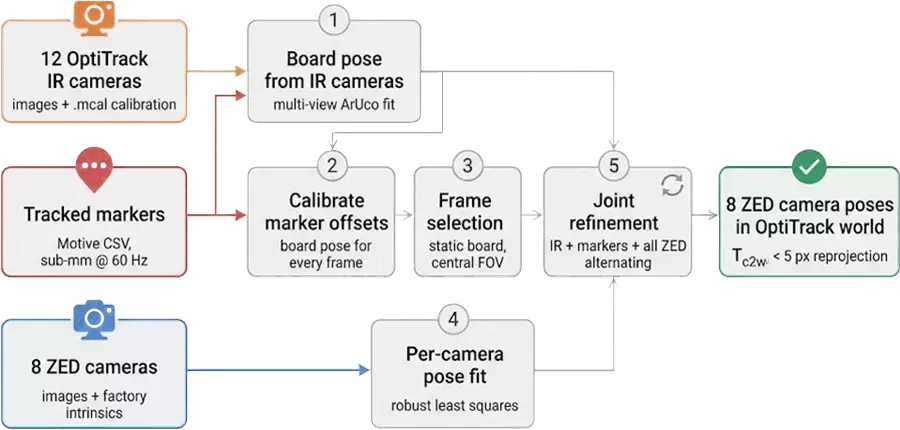
Step 1: Board Poses from the Infrared Cameras
The IR camera poses come straight from the .mcal file, with one correction: Motive exports each camera’s orientation in an OpenGL-style convention (+Y up, −Z forward), so each rotation is right-multiplied by a diag(1, -1, -1) flip, negating the Y and Z axes, before the extrinsics make sense to OpenCV. With that fixed, every infrared image goes through ArUco detection, and for each frame the board pose is fitted jointly across all IR cameras that see it: detected corners are undistorted, every corner observed by at least two cameras is triangulated2, a Procrustes fit3 against the known board geometry gives an initial pose, and a joint Levenberg–Marquardt refinement minimizes reprojection error across all observing cameras, dropping cameras whose residuals stay large.
Initializing by triangulation rather than per-camera PnP is deliberate: a planar target seen from overhead cameras is exactly the geometry where PnP’s two-fold planar ambiguity4 bites, and triangulation sidesteps it entirely.
Each fitted pose is then verified against the tracked markers: every marker must lie within 150 mm of one of the board’s physical corners. Poses that disagree are rejected. This is what the four markers are really for. The surviving ~3,900 poses still carry the .mcal noise (the IR reprojection residual is around 7–8 px), which is fine: they are never used individually, only in aggregate, in the next step.
Step 2: Where Are the Markers, Exactly?
For each verified frame, the tracked marker positions are transformed into the board frame. Per frame they scatter by a couple of centimeters (the .mcal noise again), but the scatter is largely random, so the median over ~3,900 poses pins each marker down to millimeter level. The recovered positions pass the physical sanity check: four points at the four board corners, sitting about 2.5 cm above the surface, which matches the ball-tipped pins they’re mounted on.
Once the marker offsets are known, the markers alone are enough: a simple Procrustes fit of the four calibrated offsets to the four tracked positions yields the board pose for every frame, at the full OptiTrack frame rate, with sub-millimeter internal consistency, including frames where no infrared image was saved. The board pose is no longer limited by the .mcal quality at all.
Step 3: Keeping Only the Frames You Can Trust
This step came out of data analysis rather than design, and it improved the results more than anything else. Binning the reprojection residuals against everything measurable exposed two clean structures:
- Board motion. Residuals grow with board speed, and much more steeply for some cameras than others. With the board stationary, every camera was accurate. So the calibration only uses frames where the board was effectively at rest (under 50 mm/s). There are plenty: the board was set down at many spots around the room, and every camera sees it static at several distinct placements.
- Field-of-view edges. Detections far from the image center carry much larger errors, a mix of distortion-model limits and oblique viewing angles degrading corner localization. Tags beyond a fixed radius from the principal point (700 px here) are dropped, which discards only a few percent of the detections but removes a heavy error tail.
The general lesson: frames where the systems disagree don’t have to be explained; they have to be excluded. The calibration needs accurate frames, not all frames.
Step 4: Fitting Each Camera
With a precise board pose per frame and a cleaned frame set, each ZED camera is fitted independently. Per-frame PnP gives candidate camera poses through the chain formula above; the median position cluster of those candidates provides a robust initialization, and a single robust least-squares solve (soft-L1 loss) over all board corners in all of the camera’s frames optimizes the 6-DOF pose. Frames whose residual stays far above the camera’s median are trimmed once, and the solve is repeated.
Before any of this, 20% of frames are split off as a holdout set that the optimization never touches.
Step 5: Joint Refinement
Up to here, each frame’s board pose comes from the four markers alone. The final stage re-estimates every frame’s board pose from everything that observed that instant (the infrared cameras, the markers, and all eight ZED cameras), alternating with per-camera pose refits.
One detail matters a lot: the marker term must stay dominant in this optimization (here it carries about 20× the weight of the infrared term). The Motive marker world is the ground truth that downstream users live in. With a weak anchor, the consensus drifts toward whatever the best-covered cameras prefer: training residuals improve while the cameras with the fewest observations get worse against the marker world. The marker offsets are also re-estimated each round, since the initial values inherited a small systematic bias from the .mcal calibration.
The holdout stays clean throughout: a holdout frame’s pose is never refined with its own ZED detections, and the final evaluation is always against poses derived purely from the tracked markers, the same world any consumer of this calibration will use.
Results
Final reprojection errors, with the holdout set evaluated against board poses derived purely from the tracked markers:
| Camera | Train median | Test median | Train frames |
|---|---|---|---|
| zed0 | 1.45 px | 2.10 px | 180 |
| zed1 | 2.29 px | 2.72 px | 627 |
| zed2 | 1.74 px | 1.85 px | 687 |
| zed3 | 1.98 px | 2.96 px | 1,009 |
| zed4 | 1.16 px | 1.15 px | 188 |
| zed5 | 1.81 px | 2.91 px | 1,428 |
| zed6 | 2.07 px | 3.24 px | 1,100 |
| zed7 | 2.97 px | 4.27 px | 440 |
All eight cameras come in below 5 px on holdout, averaging under 3 px. At the typical 2.5–3 m board distance that corresponds to roughly a centimeter of 3D error. The test numbers run slightly above train, which is expected since the joint refinement adapts the training-frame poses; the holdout column is the one to trust.
On intrinsics. The ZED factory intrinsics are used exactly as shipped; the calibration solves for poses only. Subpixel corner refinement was also tested and changed nothing measurable, so corner detection is not where the remaining error lives.
Lessons Learned
Bin your residuals against everything. The single most productive debugging tool was not theorizing about error sources but slicing the reprojection residuals against every variable available: board speed, distance, position in the image, tag size, time. Both of the big wins in Step 3 fell out of a table within minutes of making it.
Not all frames deserve to be fitted. It’s tempting to feed the optimizer everything and trust the robust loss. But a robust loss only protects against outliers, not against a systematic error population: frames captured under conditions where some cameras are reliably wrong will bend the solution. Identifying those conditions and excluding them beats down-weighting them.
Forex board, not paper. Under OptiTrack’s infrared illumination, standard white paper tends to wash out completely. Forex has better near-infrared reflectance and stays patterned enough for ArUco detection. Even with forex, gamma correction on the OptiTrack images helps as a fallback when detection fails.
Verify against an independent measurement. Before their positions on the board were calibrated, the markers couldn’t provide a usable board pose on their own, but they could already serve as a referee: every IR-fitted pose has to agree with them or it’s thrown out. The check is cheap, and it catches failure modes that are invisible from reprojection error alone.
Limitations, and What I’d Do Differently
The remaining error is systematic rather than noise: running more frames through the same pipeline won’t reduce it. Getting below the current level is a capture problem, not an algorithm problem.
- A stiffer board. At this target size, a few millimeters of bow across the board translates directly into pixel-level reprojection error. A more rigid substrate (aluminum composite, glass-mounted print), or explicitly calibrating the board’s surface deformation, is the first thing I’d change.
- A better marker rig. The markers are the source of ground truth for the whole calibration, and right now there are only four of them, hand-taped and coplanar. Rigid mounts, more markers, and some height variation would strengthen the board-pose anchor considerably.
- A fresher mocap calibration. The infrared cameras’ own calibration showed measurable internal inconsistency and a systematic offset against the marker world. Re-running the wand calibration immediately before the capture session would tighten the IR side and let it carry more weight in the refinement.
- A deliberate capture protocol. Since only static-board frames contribute, slowly sweeping the board around is mostly wasted motion. The efficient protocol is place, pause, move: set the board down, hold for a few seconds, relocate, and cover each camera’s central field of view at several distances and orientations.
Conclusion
The approach here sidesteps the co-visibility problem by using the OptiTrack infrastructure as a calibration scaffold. Instead of requiring cameras to share a common field of view, the calibration board acts as a physical link visible to all three observers at once: to the RGB cameras and the infrared cameras through the ArUco pattern, and to the tracking system through its markers. The infrared cameras calibrate where the markers sit on the board, the markers then anchor the board’s pose in every frame, and each ZED camera is calibrated against that marker-anchored trajectory, with no direct overlap between ZED cameras required.
The final output is a pose for each of the 8 ZED cameras in the OptiTrack world frame, which makes it possible to project any tracked 3D position onto the right pixel in any camera.
S. Garrido-Jurado, R. Muñoz-Salinas, F. J. Madrid-Cuevas, and M. J. Marín-Jiménez, “Automatic generation and detection of highly reliable fiducial markers under occlusion”, Pattern Recognition, vol. 47, no. 6, pp. 2280–2292, 2014. ↩︎
R. Hartley and A. Zisserman, Multiple View Geometry in Computer Vision, 2nd ed. Cambridge University Press, 2004. ↩︎
S. Umeyama, “Least-squares estimation of transformation parameters between two point patterns”, IEEE Transactions on Pattern Analysis and Machine Intelligence, vol. 13, no. 4, pp. 376–380, 1991. ↩︎
G. Schweighofer and A. Pinz, “Robust pose estimation from a planar target”, IEEE Transactions on Pattern Analysis and Machine Intelligence, vol. 28, no. 12, pp. 2024–2030, 2006. ↩︎
The Disqus comment system is loading ...
If the message does not appear, please check your Disqus configuration.