Always Moving: 6D Poses for a Wearable Fisheye Rig
In the last post I calibrated eight ZED cameras bolted to a room’s walls so OptiTrack’s 3D positions could be projected onto each image. Those cameras never moved: one 6-DOF pose per camera is the whole answer.
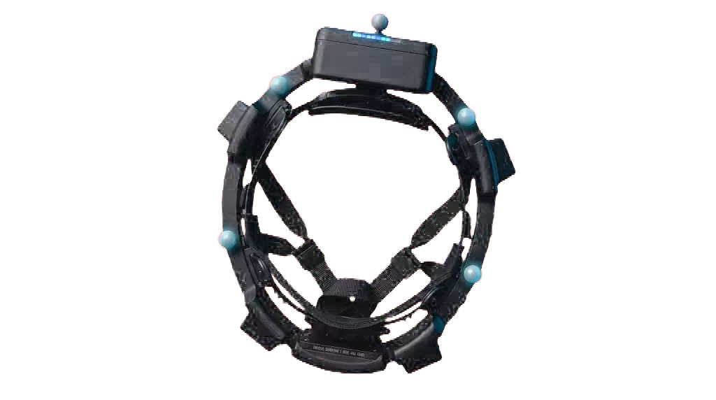
This post is the opposite case: a rig worn on a person, moving every frame. The goal is the same, but “the pose” is now a trajectory recovered at 20 Hz for the entire take, which changes which tools work. The rig is Homie, Ropedia’s four-camera egocentric setup for recording manipulation data: a person wears it, does a task with their hands, and we want every tracked object and finger marker to land on the right pixel.
Background
The rig has four fisheye cameras: a front pair looking down at the hands and work surface, and a back pair looking down and behind. The front pair overlaps heavily, the back pair overlaps each other, but front and back share almost nothing. They ship factory-rectified to 90° pinhole crops, but for pose estimation we use the raw fisheye frames to keep the full field of view.
The four cameras are calibrated once with Kalibr: each is a Kannala–Brandt (equidistant) fisheye, and the rigid transforms between them are fixed forever because they share one chassis. The only thing that changes is where the chassis is.
OptiTrack reports the 3D positions of retroreflective markers in a global world frame $W$ at 60 Hz. To project those onto a Homie image we need, for camera $c$ at time $t$, the world-to-camera transform $T_{W\to c}(t)$. A world point $p$ then lands at $\pi_c\!\big(T_{W\to c}(t)\,p\big)$, where $\pi_c$ is the Kannala–Brandt projection.
Why Not Pure Vision?
The obvious instinct is to throw the four video streams at SLAM or structure-from-motion and read off the trajectory. We considered it, and it’s the wrong tool here, for reasons specific to egocentric capture:
The cameras mostly see the wearer. The front pair is dominated by the person’s own arms and hands; the back pair by their torso, head, and hair. The static scene SLAM needs is what’s left at the edges. Worse, the foreground is adversarial: arms move independently of the head, so feature tracks on them violate the rigid-scene assumption. Most of your robustness budget goes to rejecting the wearer.
The manipulated objects move too. The whole point of the take is moving cups, plants, and tools around, each a moving rigid body in the middle of the frame.
The two pairs don’t share a view. Using all four needs a generalized multi-camera formulation with the rig extrinsics baked in, and front and back never co-observe a landmark, so they constrain each other only through the rig.
Downward egocentric motion is near-degenerate. Cameras pointed at floor and countertop see repetitive texture under fast, mostly-rotational motion with blur and rolling shutter, exactly where monocular scale drifts and tracking breaks.
And the part that kills it for our goal:
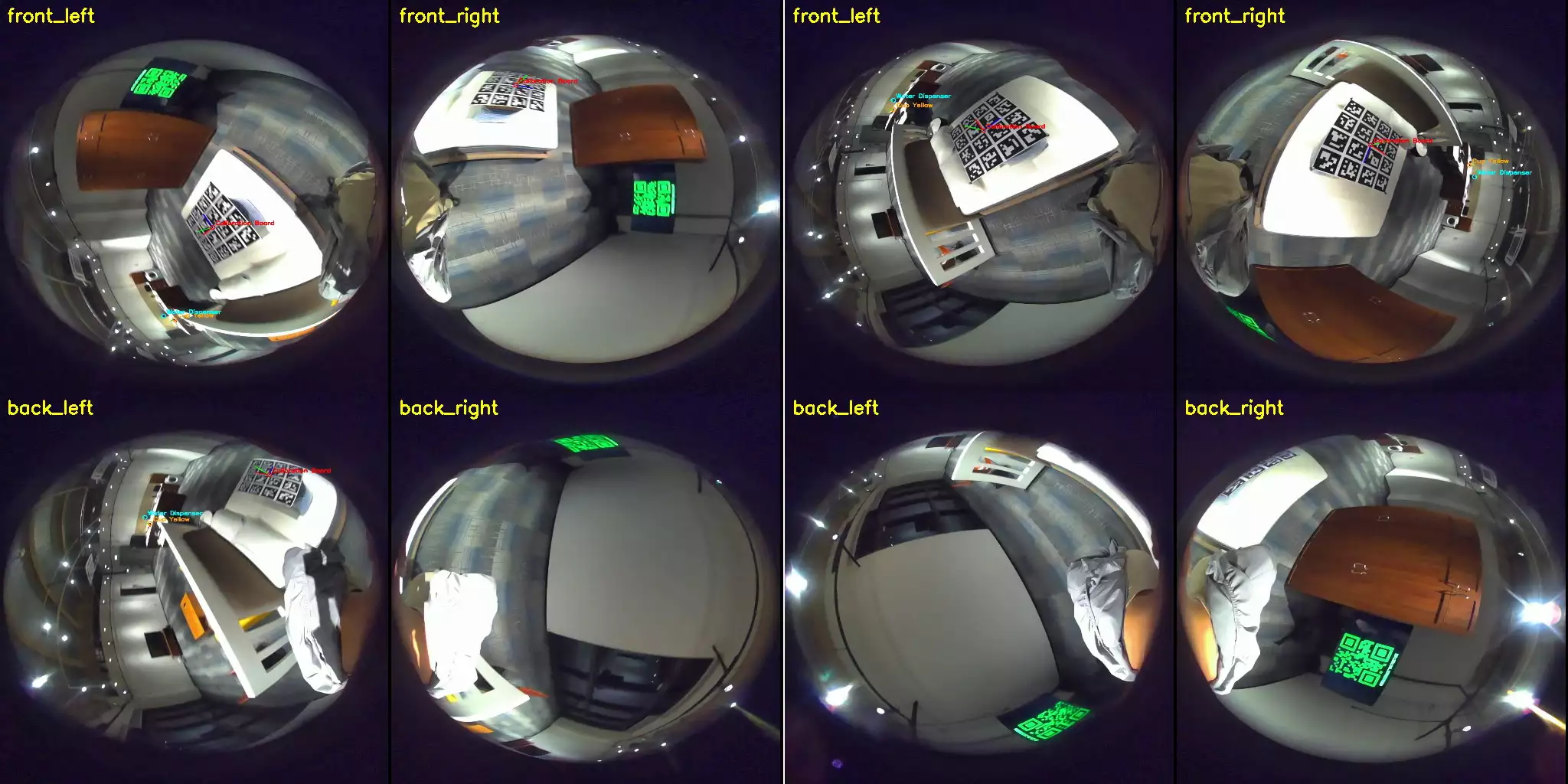
Vision gives a trajectory in the wrong frame, with too thin a bridge to OptiTrack. Even a perfect SLAM run produces poses in its own arbitrary, drifting frame $W'$, not the OptiTrack world $W$ we need. Aligning $W' \to W$ needs frames where a camera sees a world-anchored reference: our ArUco board. So I measured how often the board is visible during a real task take (not a calibration session):
| View | frames with ≥4 tags (PnP-able) | when |
|---|---|---|
| front_left | 4.3% | only the first and last ~20% |
| front_right | 4.6% | only the first and last ~20% |
| back_left | ~0% (max 2 tags) | never |
| back_right | ~0% (max 2 tags) | never |
The board is visible only at the start and end and nowhere across the middle of the take. That’s the natural behavior of glancing at a reference, doing the task, glancing again. A vision trajectory would be pinned at both ends and left to drift unobserved across the entire task in between. That middle is exactly the part we care about, and exactly the part with no anchor to validate against.
The conclusion wrote itself: don’t estimate the rig’s motion from what it sees. Measure it directly.
The Idea: Make the Rig a Tracked Body
OptiTrack is already in the room, running at 60 Hz, sub-millimeter. So we glue a small constellation of retroreflective markers onto the Homie chassis and register it in Motive as a rigid body, Homie. Now OptiTrack tracks the rig itself every frame, independent of what the cameras see.
That gives $T_{H\to W}(t)$, the pose of the rig body $H$ in the world $W$, for free. What’s missing is the fixed transform from each camera to the body frame, the hand-eye transform $T_{c\to H}$. With it, every camera’s pose is a one-liner:
$$T_{c\to W}(t) = T_{H\to W}(t)\,\cdot\,T_{c\to H}, \qquad T_{W\to c}(t) = T_{c\to H}^{-1}\,\cdot\,T_{H\to W}(t)^{-1}.$$No board, no SLAM, no drift at inference: just a CSV lookup and a matrix multiply.
A common worry: the markers are taped on by hand, so the body frame is arbitrary. It doesn’t matter: we never assume where the markers are, we calibrate $T_{c\to H}$ against whatever frame they define, so any crookedness is absorbed exactly. (Same philosophy as the previous post’s marker-offset calibration: don’t measure the rig, solve for it.) It also makes the result robust to the rig shifting slightly on the body, since we track the rig, not the person.
Hand-eye calibration is textbook (Tsai–Lenz1, Park2). The work isn’t the algorithm; it’s making it trustworthy on a moving four-fisheye rig and knowing what the residual error means.
Hardware and Calibration Target
Cameras. Four fisheye cameras at 1088 × 1280, Kannala–Brandt, calibrated together with Kalibr (intrinsics, distortion, inter-camera extrinsics), recording at 20 Hz.
Board. The same target as the previous post: a 4 × 4 grid of ArUco markers3 (DICT_6X6_100, IDs 0–15), 125 mm tags with 25 mm gaps, on a forex board. Only its corner layout is reused; the board’s world pose $T_{B\to W}$ is not assumed here; it’s solved jointly in the bundle adjustment (Step 3), so the board can sit anywhere in the room, as long as it stays put during the take.
Rig body. Five markers on the Homie chassis, registered as the Homie rigid body in Motive: five, not the minimum three, so the body keeps tracking when an arm or the head occludes one or two.
Synchronized Capture
Everything from the previous post about not trusting timestamps applies, and it matters more here because the rig moves fast: at 100 °/s, a 10 ms timing error is already a degree of pose error. The pipeline reuses the QR-clock optical sync: a nanosecond clock rendered on the Motive PC’s monitor and decoded from the frames. Since the rig is worn and its cameras face the hands and the wearer’s back, they never catch that monitor during the task, so at the start of the take the wearer briefly points one camera at it to capture the clock. From there the offset is folded into the sync table, mapping every Homie frame to an OptiTrack frame. Residual global delay is ~0 and the four cameras are mutually synced to under 2 ms.
I don’t trust “already folded in,” so the calibration also solves a small per-camera time offset as a free parameter (below). The fitted values (+2.0, +2.0, +3.3, +1.9 ms) are small, confirming the sync did its job. Had they come back at tens of milliseconds, the calibration would have flagged a broken sync instead of silently baking in the error.
The Calibration Pipeline
The whole pipeline is one script that turns a single calibration take into the four hand-eye transforms $T_{c\to H}$, one per camera. It needs the Homie fisheye frames, the Motive export (the Homie body track and the board-marker positions), the Kalibr chain, and the sync table.
Step 1: Board pose per camera, in fisheye
For each camera and frame, detect the ArUco board and recover $T_{B\to c}$, the pose of the board frame $B$ in the camera $c$. The board is planar and often seen obliquely through a fisheye lens, the textbook trap for PnP’s two-fold planar ambiguity. So the corners are undistorted through the Kannala–Brandt model, then solved with IPPE (the planar PnP that returns both branches), keeping the lower-reprojection one:
und = cv2.fisheye.undistortPoints(corners.reshape(-1, 1, 2), K, D)
n, rvecs, tvecs, errs = cv2.solvePnPGeneric(
    obj_pts, und, np.eye(3), None, flags=cv2.SOLVEPNP_IPPE)
# keep the in-front branch with the smaller reprojection error
Frames with reprojection above 2 px are dropped on the spot; surviving wrong-branch frames are mopped up later by the robust loss in the joint solve.
Step 2: Hand-eye initialization
Each camera now has a stream of paired transforms: $T_{H\to W}(t)$ from OptiTrack and $T_{B\to c}(t)$ from the board. The board is static, so these are exactly what cv2.calibrateHandEye wants, and the Park method gives a clean initial $T_{c\to H}$ per camera:
R_c2h, t_c2h = cv2.calibrateHandEye(
    R_h2w, t_h2w,        # gripper (Homie body) -> base (world)
    R_b2c, t_b2c,        # target (board) -> camera
    method=cv2.CALIB_HAND_EYE_PARK)
A nice consequence of one shared static board: only one camera strictly needs to see it, since the rest are tied to it through the rig. In practice a good take has the wearer slowly turn in place so each camera sweeps across the fixed board, so all four collect hundreds of views, but the geometry degrades gracefully if one camera barely sees it.
Step 3: One joint bundle adjustment
The per-camera fits are independent and don’t know the board is one physical object. The final step ties everything together in a single non-linear least squares over:
- the four $T_{c\to H}$ (6 DOF each),
- the one static board pose $T_{B\to W}$ (6 DOF, shared by all cameras), and
- the four per-camera time offsets (1 each).
The residual is the fisheye reprojection of the board corners, across every camera and frame, under a robust soft-L1 loss:
$$\min_{\{T_{c\to H}\},\,T_{B\to W},\,\{\delta t_c\}} \;\sum_{c,\,t}\;\rho\Big(\big\|\,\pi_c\big(T_{c\to H}^{-1}\,T_{H\to W}(t+\delta t_c)^{-1}\,T_{B\to W}\,X_B\big)\;-\;u_{c,t}\,\big\|\Big)$$where $X_B$ are the known board corners and $u_{c,t}$ the detected pixels. The shared board pose makes the four cameras mutually consistent; the soft-L1 loss absorbs residual PnP-branch flips as outliers.
One decisive choice: fit only on low-angular-velocity frames. The largest error source on a moving rig is residual time misalignment between camera and mocap, and its effect scales with rotation speed. Fitting on slow frames keeps that contamination out of the parameters, while all frames are used for evaluation, the separation that makes the next section honest.
Results
On a deliberate session (the wearer slowly turning so each camera sweeps the fixed board), 1,763 board views, the joint solve drops the overall median reprojection from 5.4 px at init to 1.94 px. One thing to read correctly: this reprojection is the full-chain residual (board corners pushed through OptiTrack’s rig pose, the shared board pose, and the hand-eye transform), not the per-frame PnP fit that the 2 px filter in Step 1 used. It’s a stiffer test, so these numbers can legitimately sit above that 2 px cutoff.
| Camera | Views | Median reproj | Low-motion median |
|---|---|---|---|
| front_left | 412 | 1.80 px | 1.75 px |
| front_right | 522 | 1.97 px | 1.78 px |
| back_left | 403 | 1.76 px | 1.58 px |
| back_right | 426 | 2.56 px | 2.17 px |
All four land near 2 px; back_left even matches the front pair. The one outlier is back_right at ~2.5 px, which traces to that camera’s own intrinsics/geometry rather than the sync (its fitted time offset came back ≈0, verified separately). The real headline is that the back pair calibrates at all: in a calibration session you can make every camera see the board, even though in a real task take (the earlier table) they never do. That’s the whole advantage of decoupling calibration from inference.
The most informative view is reprojection error binned against angular velocity:
| Homie angular velocity | n | Median reproj | p90 |
|---|---|---|---|
| 0–10 °/s | 149 | 1.70 px | 2.70 px |
| 10–25 °/s | 713 | 1.84 px | 3.54 px |
| 25–50 °/s | 613 | 1.97 px | 4.55 px |
| 50–100 °/s | 248 | 2.47 px | 6.62 px |
| 100+ °/s | 40 | 3.25 px | 7.43 px |
This is the OptiTrack-plus-sync quality floor made visible. Nearly still, error sits at 1.7 px, the calibration’s own accuracy. As the rig spins faster it climbs smoothly, the signature of residual timing/interpolation error, not a calibration mistake. No optimization moves the slow-motion number; the fast-motion number is a capture-and-sync problem.
Inference
With $T_{c\to H}$ baked in, per-frame poses for any take need no images: only the Homie body track and the sync table. The one wrinkle: cameras (20 Hz) and OptiTrack (60 Hz) don’t share timestamps, so the body pose is interpolated at each camera time with SLERP on rotation and linear on translation:
def pose_at(self, tq):
    T = np.eye(4)
    T[:3, :3] = self.slerp([tq]).as_matrix()[0]      # rotation: SLERP
    T[:3,  3] = [np.interp(tq, self.t, self.pos[:, i]) for i in range(3)]
    return T

# per camera, per frame:
T_c2w = homie.pose_at(t + dt[cam]) @ T_homie_cam[cam]
T_w2c = inv(T_c2w)                                    # world -> camera, for projection
The output is a JSON of $T_{W\to c}$ for every frame and camera, in the OptiTrack world frame, in millimeters, exactly what a consumer needs to drop a tracked 3D point onto the right pixel.
Lessons Learned
Bin residuals against angular velocity. Same lesson as last time, different axis: on a static rig the revealing variable was board speed; on a worn rig it’s the rig’s rotation speed. The binned table separates “how good is my calibration” (the slow bin) from “how good is my sync” (the slope), and tells you which to fix.
Calibrate the mount, don’t measure it. Hand-taping markers onto a chassis introduces an unknown, not an error, and unknowns get solved. The crooked placement is absorbed into $T_{c\to H}$ and never reaches the output.
One tracked body beats a perfect SLAM. Once the rig is a mocap rigid body, the drift problem evaporates and inference becomes a matrix multiply. For ground-truth generation, measuring the platform directly beats inferring its motion from cameras that mostly see the wearer.
Decouple calibration from inference. During calibration you control the scene and make every camera see the board; during the real task the board is essentially invisible, especially to the back cameras. Since the only thing carried over is the fixed $T_{c\to H}$, that brutal real-take visibility doesn’t matter.
Limitations, and What I’d Do Differently
The residual error here is capture, not algorithm; the diagnostics above already point at where it’s worst. Four things I’d tighten next (all keep OptiTrack in the loop; this generates ground truth, it isn’t live self-localization):
- Sync at speed. The high-velocity error floor is timing, not geometry. Tighter hardware sync (or a rolling-shutter-aware model) would flatten the curve.
- Body tracking dropouts. Inference is only as continuous as the
Homietrack. More markers, placed with the cameras’ occlusion patterns in mind, keep the body alive through the worst poses. - Rolling shutter and motion blur. At task speeds the fisheye rows aren’t exposed at one instant; a per-row time model would help the fastest frames.
- A dedicated calibration protocol. Pausing beats a continuous sweep: with the board fixed in the room, hold each camera steady on it in its central field at a few distances, the low-motion, low-distortion regime the fit trusts.
Conclusion
The previous post linked static wall cameras to OptiTrack via a shared board. This one handles cameras that move every frame by flipping the strategy: instead of asking the cameras where they are, we make the rig a tracked object and ask OptiTrack. A one-time hand-eye calibration ties each fisheye to the rig body; from then on, every pose at every instant is a lookup and a multiply, drift-free and board-free.
None of the ingredients (hand-eye, fiducial PnP, bundle adjustment) are new. The value is the integration and the diagnostics: that pure vision can’t anchor the middle of an egocentric take, that a tracked rig body sidesteps the problem entirely, and that binning the residual against angular velocity tells you how much error is calibration and how much is the clock.
R. Y. Tsai and R. K. Lenz, “A new technique for fully autonomous and efficient 3D robotics hand/eye calibration”, IEEE Transactions on Robotics and Automation, vol. 5, no. 3, pp. 345–358, 1989. ↩︎
F. C. Park and B. J. Martin, “Robot sensor calibration: solving AX = XB on the Euclidean group”, IEEE Transactions on Robotics and Automation, vol. 10, no. 5, pp. 717–721, 1994. ↩︎
S. Garrido-Jurado, R. Muñoz-Salinas, F. J. Madrid-Cano, and R. Medina-Carnicer, “Automatic generation and detection of highly reliable fiducial markers under occlusion”, Pattern Recognition, vol. 47, no. 6, pp. 2280–2292, 2014. ↩︎
The Disqus comment system is loading ...
If the message does not appear, please check your Disqus configuration.